Upflow CPI
UPFLOW CPI
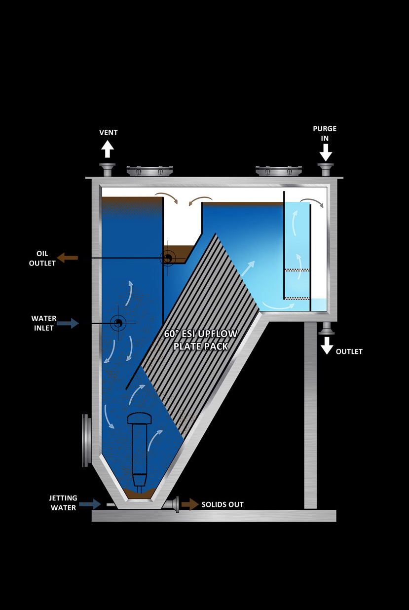
Principle of Operation
This ESI CPI separator is generally considered an “upflow” separator. The CPI “Pack” is designed to function installed at an angle of 60 degrees to the horizontal plane with plates spaced 25mm to minimize plugging. Water enters the inlet nozzle and distribution header low in the primary solids/sludge chamber. The heaviest solids/sludge settle in the primary chamber for discharge through the clean out nozzle. Water flows down and through the perforated distribution baffle. The contaminated liquid enters from the bottom of the pack and flows up through the pack end. Solids accumulate on the plates and counterflows the waste flow to the bottom of the plates.
The oil moves with the water flow to a level above the plates where a thick layer is allowed to collect until it overflows from the adjustable V-notch oil weir and into the oil collection chamber for removal. Light solids/sludge separation is simultaneously accomplished within the pack and these solids are directed to the secondary sludge sump via the vertical sludge gutters at the bottom of the pack. Treated water flows upward over a fixed water weir into the clean water collection chamber for removal. The gasketed lid allows for a gas blanket operation up to 10 ounces maximum test pressure. The gas vent allows for venting to a closed system.
This type of CPI can be fitted with a sand cleaner which uses high pressure water to blast the oil wet sand particles into a header where the oil is knocked loose from the sand.
CPI Downflow Oil Remover